

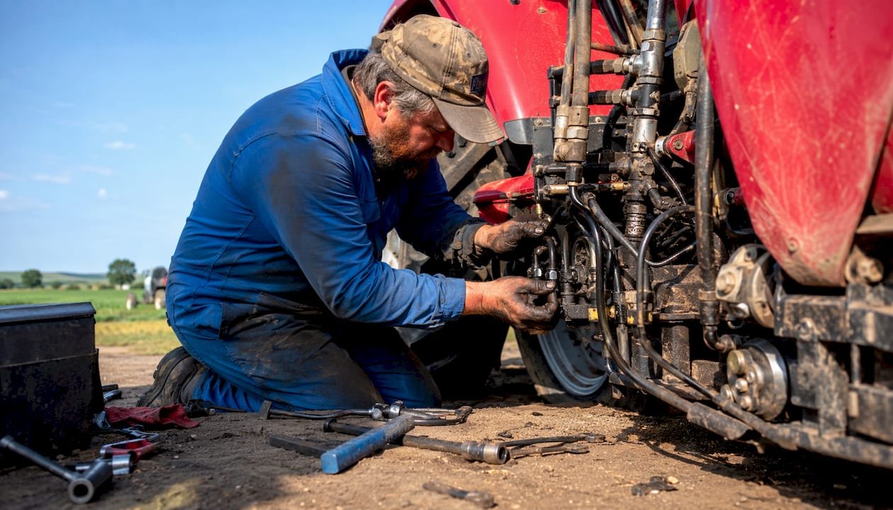
Hydraulic system failures account for a significant portion of agricultural machinery breakdowns, and catching symptoms early can greatly reduce costly downtime. Here is link to solve any problem with your tractor or any Agriculture equipment https://repairmanualnow.com/product-category/agriculture/ Most tractor hydraulic problems trace back to four root causes: fluid contamination, internal leakage, overheating, or worn seals and hoses. Before you pull a pump or condemn a cylinder, run through these quick checks first:
- Fluid level: Low fluid causes more “weak hydraulics” complaints than any other single factor. Check it warm, on level ground.
- Control lever position: On 3-point hitch systems, a misadjusted draft control lever is a common cause of no-lift complaints and costs nothing to fix.
- Hydraulic filter condition: A filter at bypass starves the pump of inlet flow and mimics a failed pump exactly.
- Visible leaks: Wipe fittings and hose ends clean, run the system under load, and watch where fluid reappears.
- Abnormal noises: A high-pitched whine signals cavitation; a knocking or banging sound points to aeration or a failing pump.
If all five check out and the problem persists, the fault is deeper in the circuit. The sections below walk you through every layer, from system fundamentals to professional-grade thermal diagnosis.
How tractor hydraulic systems work, and why it matters for diagnosis
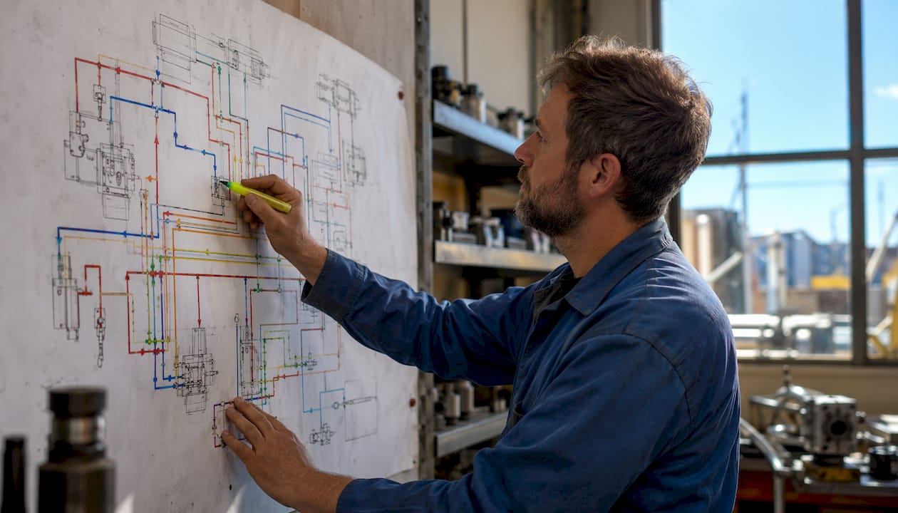
Understanding the flow path is the fastest way to narrow down where a fault lives. A tractor hydraulic system moves pressurized fluid from a reservoir through a pump, then through directional control valves, and finally into actuators such as lift cylinders or hydraulic motors. Each component in that chain has a defined pressure and flow role, and a failure at any point produces a predictable symptom pattern downstream.
| Component | Function | Common failure mode |
|---|---|---|
| Hydraulic pump | Generates flow and pressure | Worn internals, cavitation, drive failure |
| Relief valve | Caps maximum system pressure | Stuck open (low pressure), stuck closed (overheating) |
| Directional control valve | Routes flow to actuators | Spool sticking, internal seal wear |
| Lift cylinder | Converts pressure to mechanical force | Piston seal bypass, rod seal leak |
| Hydraulic filter | Removes particulate contamination | Clogging, bypass valve stuck open |
| Reservoir and hoses | Store and transport fluid | Contamination ingress, hose chafing, fitting leaks |
Relief valve settings sit at the center of many tractor hydraulic failures. Too-low pressure causes power loss at external couplers; too-high pressure accelerates oil overheating and seal damage. On most agricultural tractors, working pressure at the external quick couplers runs within a typical range, and pressure above a certain threshold pushes the system into the overheating zone.
Knowing which block of the circuit is healthy and which is not lets you divide and conquer rather than replace parts at random.
Common hydraulic system problems and what they look like
Tractor hydraulic failures follow recognizable patterns. Matching the symptom to the circuit block saves hours of guesswork.
Leaks
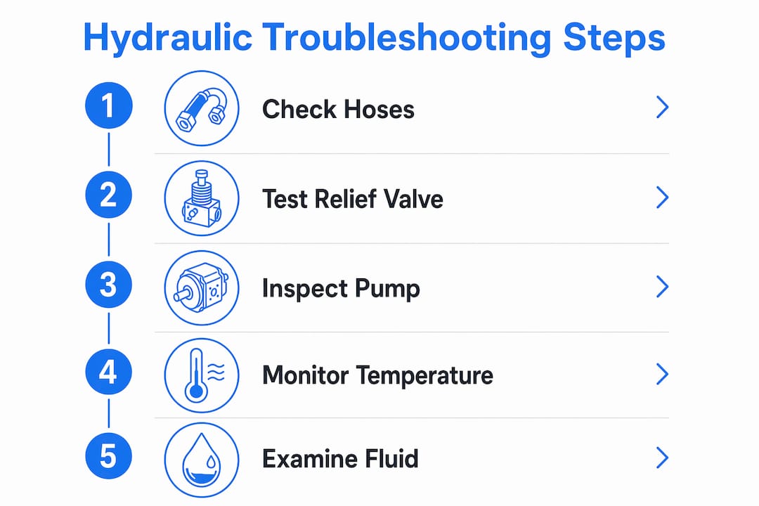
Hoses and fittings are the most common failure points in tractor hydraulics. Correct routing and securing make a measurable difference in service life. External leaks are visible at fittings, hose ends, cylinder rod seals, and quick couplers. Internal leaks are harder to find because the fluid bypasses internally rather than escaping the circuit. A cylinder that raises normally then drifts down under load is the classic internal leak signature.
Overheating
Heat buildup typically indicates internal leakage, restricted flow, or a relief valve that is continuously bypassing rather than a simple cooling failure. Oil temperature exceeding 185–195°F above ambient causes the fluid to lose its lubricating properties, which accelerates pump and valve wear in a self-reinforcing cycle.

Fluid contamination
Contamination from water, dirt, and metal particles severely accelerates seal wear and component damage. Milky oil signals water intrusion. Dark or black oil indicates dirt and oxidation. Shiny metallic flecks in a fluid sample mean metal wear debris is circulating through the system. One expert described contaminated oil as “liquid sandpaper running through your system,” and that description is accurate at the component level.
Cavitation and aeration
Cavitation forms when pump inlet pressure drops too low, creating vapor bubbles that collapse violently against internal surfaces. Aeration occurs when air enters the suction side past a leaking fitting or low fluid level. Both produce whining, banging, or chattering noises and cause jerky, inconsistent actuator movement. Cavitation can destroy a pump in a single shift if the suction restriction is severe.
Common symptoms mapped to causes:
- Slow lift across all functions: worn pump, low fluid, or plugged suction filter
- One function slow, others normal: bypassing cylinder seal or spool valve fault in that circuit branch
- 3 point hitch not working or dropping under load: rockshaft seal wear, control valve leak, or draft control misadjustment
- Erratic or jerky cylinder movement: aeration or contaminated fluid affecting valve response
- Noisy pump operation: cavitation, suction restriction, or low oil level
- System slips or loses pressure under load: relief valve set too low or passing early
Hydraulic pump issues deserve specific attention. Pumps account for a notable share of system problems, with overload during heavy front-loader use and obstructed suction lines being common precursors to failure.
Step-by-step troubleshooting techniques for tractor hydraulics
The sequence that saves the most time is: electrical first, mechanical second, hydraulic third. Many hydraulic failures result from external electrical or mechanical faults rather than pump defects, and misdiagnosis leads to expensive, unnecessary part replacements.
Tools you need before you start:
- Pressure gauge rated for your system’s working pressure
- Infrared thermometer or thermal camera
- Dipstick and clean fluid sample container
- Flashlight for visual inspection of hose routing and fittings
- Flowmeter rated for 40–60 gpm and 3,000–5,000 psi for pump output testing
Inspection sequence:
- Check electrical controls first. Verify solenoid coils, switches, and any electronic hitch control (EHC) signals are functioning. A failed coil or broken wire produces classic hydraulic symptoms without touching the fluid circuit.
- Inspect mechanical linkages. A bent rod, seized pivot, or misaligned coupling can produce slow or no-movement symptoms that look hydraulic. Check draft control linkage, top link length, and sensing arm condition on 3-point hitch systems.
- Check fluid level and condition. Pull the dipstick warm. Assess color, smell, and clarity before anything else.
- Inspect the filter. Replace it before any further hydraulic diagnosis. A clogged filter starves the pump and mimics pump failure exactly.
- Measure pressure at test ports. With the system at operating temperature and under load, compare readings against your service manual’s specified range. Readings taken cold or unloaded can send the diagnosis in the wrong direction.
- Perform a thermal scan. Run the system under load, then use an infrared thermometer to shoot the cylinder body, relief valve, and pump case. A cylinder body warmer than the surrounding circuit points to a bypassing piston seal. A relief valve hotter than everything else means it is continuously dumping pressure.
- Conduct a cylinder leak-down test. Raise the hitch or boom with a load attached, shut the engine off, and watch for 15–20 minutes. Drift confirms internal leakage in either the cylinder or the control valve.
Pro Tip: Thermal imaging can identify internal leakage in cylinders and worn components by detecting localized heat spots before catastrophic failure occurs. A relief valve that is bypassing, a restriction across a control valve, or a motor case drain carrying too much leakage will each create a distinct local heat pattern.
Always depressurize the system before disconnecting any hydraulic line. High-pressure hydraulic fluid injection through the skin is a medical emergency, not a minor puncture wound.
Preventative maintenance practices that extend hydraulic system life
Reactive repair costs far more than scheduled maintenance. Preventive maintenance cost for a tractor hydraulic system runs well below the cost of a single pump replacement, which can reach $1,250–$3,750 depending on the model.
- Change the hydraulic filter regularly according to the manufacturer’s recommended engine hours interval. Regular filter changes and using the correct fluid specification significantly reduce failure risk and extend component life. Write the install date on the filter housing.
- Use the correct fluid specification. John Deere systems require J20C standard; New Holland specifies UTTO; Ursus equipment uses HVLP-D 46. Using outdated hydraulic fluid specifications increases the risk of hydraulic failure compared to current-standard fluids.
- Perform a complete fluid change, not just a top-up. Topping off contaminated fluid dilutes but does not eliminate the problem. Drain fully, clean the reservoir, and refill with fresh fluid meeting current OEM standards.
- Inspect hoses and fittings at every service interval. Look for chafing at routing points, proximity to heat sources, and loose clamp torque. Clearance issues are often invisible when the tractor is at rest but obvious under load.
- Monitor oil temperature during operation. Keep fluid below 185°F. Install a fluid temperature alarm if your tractor does not have one from the factory.
- Keep the reservoir vent cap clean. A clogged vent creates a vacuum condition that promotes cavitation and draws in contaminated air.
- Conduct periodic oil sampling. Routine oil sampling and contamination monitoring reveal root causes early, enabling proactive repairs before components fail. High brass content in a sample indicates wear plate degradation in the pump.
Pro Tip: Before each work season, check the oil level on a cold engine. If the level has dropped more than 10% of tank capacity since the last check, you have a leak path that also admits air, and finding it before the season starts prevents a mid-field breakdown.
| Maintenance task | Interval | Why it matters |
|---|---|---|
| Hydraulic filter replacement | At regular engine hour intervals | Prevents pump starvation and contamination circulation |
| Full fluid change | Per OEM schedule or annually | Removes accumulated contamination and degraded additives |
| Hose and fitting inspection | Every service interval | Catches chafing and routing issues before leaks develop |
| Oil sampling and analysis | Annually or after any major repair | Detects metal wear, water, and contamination early |
| Vent cap cleaning | Every service interval | Prevents vacuum-induced cavitation and contamination ingress |
| Fluid temperature check | During operation | Confirms cooling capacity and absence of internal leakage |
For model-specific service intervals and torque specifications, agriculture repair manuals provide the OEM-level detail that generic guides cannot match.
Expert insights on troubleshooting priorities and common misconceptions
The single most expensive diagnostic mistake in tractor hydraulics is replacing the pump before confirming the fault is actually in the pump. Internal leakage is a silent killer that causes efficiency loss, heat buildup, and is routinely misdiagnosed as an upstream fault, leading to unnecessary part replacements. A pump can be blamed for weak performance when the actual loss is across a cylinder piston seal or a worn valve section further downstream.
The cause-symptom table below reflects the multi-cause reality that experienced technicians navigate on every job.
| Symptom | Hydraulic cause | Mechanical cause | Electrical cause |
|---|---|---|---|
| System runs slow | Low pump output, internal leakage, relief valve passing | Binding linkage, seized bearing | Low motor supply, poor control signal |
| Actuator drifts under load | Piston seal bypass, load-holding valve leak | Worn pins or linkage play | Solenoid not fully de-energizing |
| Excessive heat | Relief valve bypassing, restricted filter, continuous internal leakage | Excessive friction, mechanical overloading | Motor overcurrent, valve chatter |
| Noisy operation | Cavitation, aeration, suction restriction | Coupling wear, loose mountings | Contactor chatter, poor coil supply |
| One function weak | Sectional valve fault, branch restriction, cylinder bypass | Bent rod, jammed guide | Failed coil, broken wire |
The “electrical first, mechanical second, hydraulic third” sequence exists because the cheapest and fastest eliminations sit outside the oil path. Verifying electrical controls and mechanical linkages before opening the hydraulic circuit consistently saves time and avoids the cost of condemning serviceable components. For Ford 7810 and similar models with complex valve stacks, model-specific service documentation is the fastest way to confirm correct pressure settings and valve configurations before any disassembly.
When to handle it yourself versus when to call a professional
Most tractor operators can handle a defined set of hydraulic repairs without specialized equipment. The boundary between DIY and professional service is not about mechanical skill alone. It is about whether you can safely diagnose the fault and whether the repair requires pressure-testing equipment or precision machining.
DIY-appropriate repairs:
- Draft control lever adjustment (free, no tools required)
- Hydraulic fluid and filter replacement
- External hose replacement with correct hose and fittings
- O-ring replacement at fittings and quick couplers
- Cylinder rod seal replacement when the rod surface is undamaged
Call a professional when:
- The system is completely dead and fluid level, filter, and pump drive have all been confirmed good
- You hear continuous cavitation (high-pitched whine or squeal) and the suction side checks out
- Fluid is foaming or running consistently hot above 185°F
- A cylinder will not hold pressure after a seal repack
- You have replaced an obvious-looking part and the symptom persists unchanged
Cylinder rebuilds, pump replacement, valve stack work, and anything requiring pressure-testing to diagnose properly fall outside what most operators can safely complete in the field. Attempting a pump replacement without also changing the fluid and filter is a specific mistake worth avoiding: a failing pump sheds metal into the oil for weeks before it actually fails, and that metal will destroy a new pump within a few hundred hours if the system is not flushed.
Common replacement parts and how to identify worn components
Knowing which parts wear first saves time when you are sourcing components before a repair.
High-wear components and their failure signatures:
- Cylinder piston seals: The primary indicator is a hitch or boom that raises normally but drifts down under load. Confirm with a leak-down test. Seal kits for most agricultural cylinders are available as OEM or aftermarket assemblies and are the correct first repair before condemning the cylinder body.
- Rod seals: Visible weeping around the rod when the cylinder is extended. If the rod surface is clean and undamaged, a rod seal replacement is straightforward. Scoring or pitting on the rod means the rod itself must be re-chromed or replaced before a new seal will hold.
- Hydraulic hoses: Chafing along the outer jacket, bulging under pressure, or weeping at the crimp ferrule. A hose that is weeping along its length rather than at a fitting is failing internally and needs full replacement, not a fitting swap.
- Relief valves: A valve stuck partially open causes chronic low pressure and slow operation. A valve stuck closed causes overheating and seal damage. Debris and varnish from degraded fluid are the most common causes of sticking. A full fluid and filter change resolves many relief valve complaints by removing the contamination holding the valve off its seat.
- Pump wear plates and vane tips: High brass or copper content in an oil sample is the early warning. By the time the pump is audibly noisy, wear is already advanced. Pump replacement should always be accompanied by a complete fluid change and new filter.
- Control valve spools: Sticking spools cause inability to raise or lower equipment. Contamination and varnish deposits are the primary cause. Inspect the valve area for debris entry, particularly on models where the valve is located under the seat.
Observing the characteristics of leaked or sampled oil gives direct clues about which component is failing. Milky oil that dissipates over time indicates cavitation. Milky oil that does not dissipate points to water intrusion. A burnt smell confirms thermal degradation from overheating.
How environmental factors affect hydraulic system performance
Operating conditions directly influence how quickly hydraulic components wear and how reliably the system performs. Temperature is the most significant variable.
Cold weather increases fluid viscosity, which restricts flow through the suction line and raises the risk of cavitation on startup. Allowing the tractor to warm up at low RPM before applying load gives the fluid time to reach operating viscosity and prevents the pump from starving. Hydraulic fluid that is too thick for the operating temperature is one of the two most common causes of cavitation, the other being a physically restricted suction line.
Hot, dry field conditions introduce a different set of problems. Dust and fine particulate suspended in the air enter the hydraulic system through the reservoir vent, through cylinder rod seals on parked equipment, and through any fitting that is not fully sealed. This is why vent cap cleanliness and rod seal condition matter more during harvest season than at any other time of year. A hydraulic filter that is 70% contaminated forces the pump to work harder and can cause a pressure drop across the entire circuit.
Humidity and wet conditions accelerate water contamination. Water in hydraulic fluid reduces lubricity, causes pitting against metal surfaces, degrades additive packages, and accelerates oxidation. As little as 1% water in hydraulic oil cuts bearing life by roughly half. Machines stored outdoors or in unheated buildings are particularly vulnerable because temperature cycling draws humid air through the vent cap as the reservoir breathes.
Altitude affects hydraulic performance less directly, but high-altitude operation reduces cooling air density, which can reduce heat exchanger efficiency and push fluid temperatures higher during sustained heavy work.
Get the exact specifications your tractor hydraulic system requires
Guessing at pressure settings, fluid specifications, or torque values costs more than the time it saves. Every tractor model has OEM-defined parameters for relief valve settings, filter change intervals, and approved fluid grades, and those parameters are not interchangeable between models or even between model years.

Repairmanualnow provides downloadable repair manuals for agricultural equipment covering hydraulic system schematics, pressure specifications, component torque values, and step-by-step disassembly procedures for major tractor brands. Whether you are diagnosing a 3-point hitch that will not lift or tracing an internal leak in a loader circuit, having the factory-level documentation means you are working from the same data the dealer technician uses, not a generic guide that may not match your specific model’s valve stack or pump configuration.
Key Takeaways
Tractor hydraulic failures are predictable and preventable when you follow a structured diagnostic sequence and maintain the system to OEM specifications.
| Point | Details |
|---|---|
| Start with the basics | Check fluid level, filter condition, and draft control position before any mechanical diagnosis. |
| Follow the right sequence | Verify electrical and mechanical causes before opening the hydraulic circuit to avoid misdiagnosis. |
| Change filters every 250 engine hours as recommended by most manufacturers. Regular filter replacement at this interval significantly reduces failure risk and extends component life | |
| Internal leakage is the hidden fault | A cylinder or valve bypassing internally causes heat buildup and slow operation, often misdiagnosed as pump failure. |
| Match fluid to OEM specification | Using an outdated fluid specification increases hydraulic failure risk by 60% compared to current-standard fluids. |
Recommended
- Agriculture Repair Manuals: Stop Farm Equipment Downtime in 2026
- Expert Repair and Maintenance Insights – SEO Optimized – Repair Manual Now | Automotive, Agriculture & Construction Manuals
- Car Service Repair Manuals: The Professional’s Guide to Technical Documentation
- Professional Repair and Maintenance Blog – SEO Optimized Resource – Repair Manual Now | Automotive, Agriculture & Construction Manuals