


The alternator testing procedure is defined as a systematic series of voltage and load measurements used to confirm whether a vehicle’s charging system delivers adequate power to the battery and electrical components. A complete test covers three stages: static battery voltage, running output voltage, and load voltage under electrical demand. Comprehensive alternator health is best verified by staged voltage tests so as not to mislabel functional alternators as faulty. Repairmanualnow provides OEM-level technical documentation that supports every step of this process, from wiring schematics to factory voltage specifications. Here is the place to guide you thrue your problems https://repairmanualnow.com/
What tools and safety measures do you need for alternator testing?
The right equipment makes the difference between a reliable diagnosis and a wasted afternoon. A digital multimeter is the core tool for every stage of the alternator testing procedure. A clamp meter is optional but useful for measuring amperage output without breaking the circuit.
Essential tools:
- Digital multimeter — measures DC voltage at the battery terminals for static, idle, and load readings
- Clamp meter — measures alternator amperage output by clamping around the output wire
- Safety glasses — protects eyes from battery acid spray or accidental sparks
- Insulated gloves — prevents electrical shock when probing live terminals
- Vehicle repair manual — provides OEM voltage specifications and wiring diagrams specific to your make and model
Safety precautions are non-negotiable before you touch any terminal. Park on a flat surface, apply the parking brake, and confirm the engine is off before connecting your multimeter probes. Work in a ventilated area because charging batteries release hydrogen gas. Keep metal tools away from the battery terminals to prevent accidental short circuits.
| Tool | Function in Testing |
|---|---|
| Digital multimeter | Reads DC voltage at battery terminals across all three test stages |
| Clamp meter | Measures amperage output at the alternator B+ output wire |
| Safety glasses | Protects eyes from battery acid and electrical arcing |
| Insulated gloves | Prevents shock when probing live terminals |
| Vehicle repair manual | Supplies OEM voltage specs and circuit diagrams for your specific vehicle |

Pro Tip: Set your multimeter to DC voltage at the 20V range before connecting probes. Connecting on the wrong setting can damage the meter and give you a false reading.
Step-by-step alternator testing procedure: static, running, and load tests
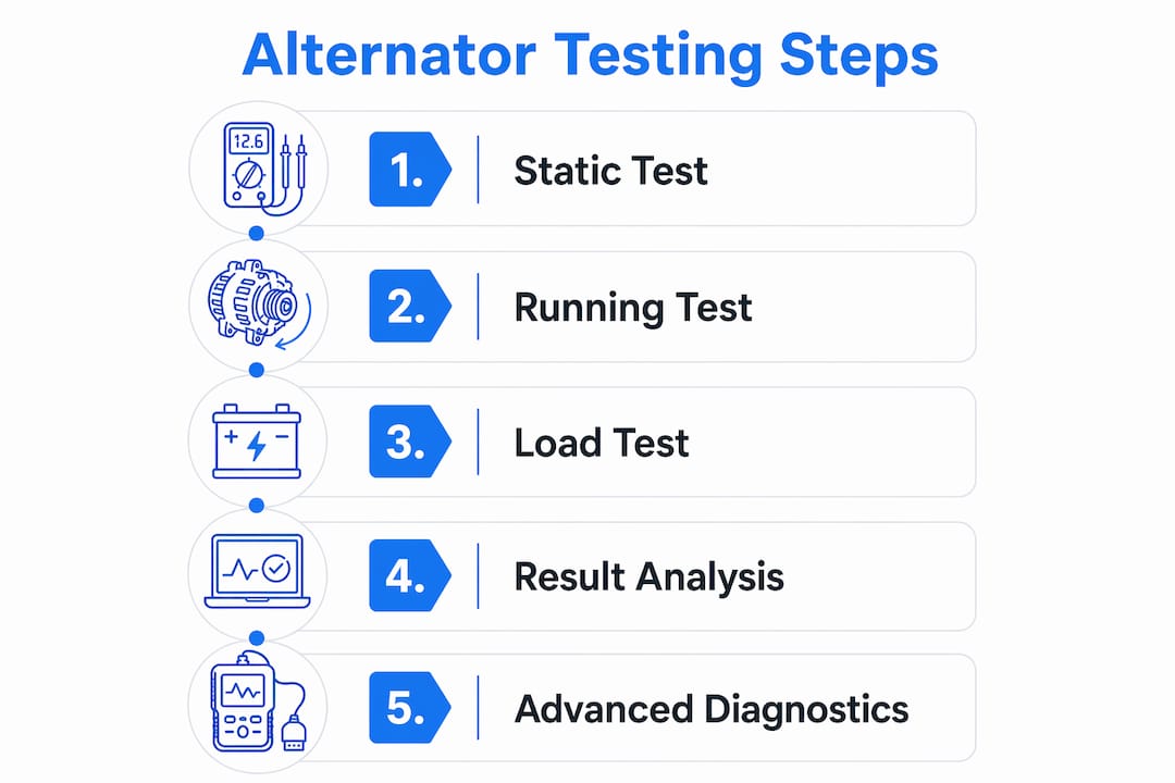
A single voltage measurement tells you almost nothing. Systematic testing at rest, idle, and load conditions avoids misdiagnosis and gives you a complete picture of charging system health. Follow these three stages in order.
Stage 1: Static battery voltage test (engine off)
- Turn off the engine and all electrical accessories.
- Set your multimeter to DC voltage, 20V range.
- Connect the red probe to the positive battery terminal and the black probe to the negative terminal.
- Read the voltage on the display.
- A healthy battery reads 12.4V–12.8V with the engine off. A reading below 12.2V indicates a weak or discharged battery. Charge the battery fully before proceeding, because a low battery will skew every subsequent reading.
Stage 2: Running voltage test (engine at idle)
- Start the engine and let it idle at approximately 700–800 RPM.
- Keep all accessories off: headlights, AC, radio, and rear defroster.
- Re-read the voltage at the battery terminals with the engine running.
- A healthy alternator produces 13.7V–14.7V at idle. A reading below 13.5V points to alternator failure. A reading above 15.0V points to a faulty voltage regulator.
Stage 3: Load test (1500–2000 RPM with accessories on)
- Rev the engine to 1,500–2,000 RPM.
- Switch on the headlights, AC blower, rear defroster, and radio simultaneously.
- Read the voltage at the battery terminals under this full electrical load.
- Voltage must stay above 13.5V under load to confirm adequate charging capacity. Falling below 13.5V reveals worn internal components or insufficient output.
| Test Stage | Normal Reading | Low Reading | High Reading |
|---|---|---|---|
| Static (engine off) | 12.4V–12.8V | Below 12.2V (weak battery) | Above 12.9V (surface charge) |
| Running at idle | 13.7V–14.7V | Below 13.5V (alternator fault) | Above 15.0V (regulator fault) |
| Load at 1,500–2,000 RPM | Above 13.5V | Below 13.5V (capacity fault) | Above 15.0V (overcharging) |
Pro Tip: Always connect the black probe first and disconnect it last. This sequence prevents accidental short circuits if the red probe touches a grounded metal surface.
How do you interpret alternator test results and identify faults?
Low voltage at idle, typically below 13.5V, points to a worn rotor, failed diodes, or a defective voltage regulator. High voltage above 15.0V is equally serious. Overcharging above 15.0V can irreversibly damage battery plates and on-board vehicle electronics in minutes, requiring urgent service action.
Unstable or fluctuating voltage readings during the idle test often indicate a failing rectifier or diode pack. A failing rectifier or diode may pass idle voltage tests but fail under real load, which is exactly why the load test at 1,500–2,000 RPM is the definitive diagnostic step. Do not skip it based on a passing idle result.
Noise is a diagnostic tool, not just a nuisance. Whining or grinding from the engine front often indicates alternator bearing failure or a slipping serpentine belt that voltage tests alone will not catch. If you hear persistent whining during the running test, inspect the belt tension and bearing condition before condemning the alternator electrically.
Use this checklist when your readings fall outside normal ranges:
- Below 12.2V static: Charge the battery fully and retest before drawing any conclusions about the alternator.
- Below 13.5V at idle: Check belt tension and terminal connections first. A loose serpentine belt reduces alternator output significantly.
- Below 13.5V under load: Suspect worn brushes, a failing diode pack, or a weak rotor winding.
- Above 15.0V at any stage: Replace or test the voltage regulator immediately. Do not drive the vehicle until resolved.
- Fluctuating voltage: Inspect ground connections and battery cable condition. Corroded or loose grounds mimic alternator failure.
- Audible whining or grinding: Inspect the serpentine belt and alternator bearing before electrical testing concludes.
You can find vehicle-specific wiring diagrams that map every ground path and charging circuit connection, which speeds up this checklist considerably.
What are advanced alternator diagnostic methods?
Standard multimeter tests cover most DIY scenarios, but some faults require additional techniques. These methods give you a complete diagnostic picture before spending money on parts.
Amperage output testing with a clamp meter:
Clamp the meter around the alternator’s B+ output wire. At 1,500–2,000 RPM with full electrical load, the alternator should produce amperage close to its rated output, which is printed on the alternator label or listed in your vehicle’s service manual. Output significantly below the rated value confirms internal wear even when voltage readings appear borderline.
Diode testing with multimeter diode mode:
- Set your multimeter to diode test mode.
- Disconnect the alternator from the circuit.
- Test each diode by placing probes in both directions across the diode terminals.
- A good diode allows current in one direction only. A reading near zero in both directions indicates a shorted diode. An open-circuit reading in both directions indicates a failed diode.
- A single bad diode causes AC ripple in the DC output, which drains the battery overnight.
Voltage drop testing along the circuit path:
Voltage drop testing along the circuit path prevents false diagnosis of alternator faults caused by corroded cables or loose connections. Measure voltage drop across each major cable segment with the engine running. A drop greater than 0.5V on any cable segment indicates resistance that reduces charging efficiency and mimics alternator failure.
When to seek professional bench testing:
DIY testing has real limits. If your readings are borderline, the diode test is inconclusive, or the vehicle has a complex smart charging system (common in post-2015 vehicles with battery management systems), professional bench testing provides a definitive verdict. A bench test loads the alternator to its full rated amperage and measures output under controlled conditions that a driveway test cannot replicate.
Pro Tip: Never disconnect the battery cable with the engine running to “test” the alternator. This outdated method can destroy the voltage regulator and damage sensitive ECU modules in milliseconds on modern vehicles.
Key Takeaways
A complete alternator testing procedure requires three staged voltage measurements, and skipping any stage risks misdiagnosis of a charging system that may actually be functional.
| Point | Details |
|---|---|
| Static voltage baseline | Confirm battery reads 12.4V–12.8V before testing; a weak battery invalidates all subsequent readings. |
| Running voltage target | A healthy alternator produces 13.7V–14.7V at idle; below 13.5V confirms a charging fault. |
| Load test is definitive | Test at 1,500–2,000 RPM with all accessories on; voltage must stay above 13.5V to confirm full capacity. |
| External faults mimic failure | Corroded cables, loose belts, and poor grounds cause a large share of diagnosed alternator failures. |
| Overcharging is urgent | Voltage above 15.0V damages battery plates and ECU modules; address it before driving the vehicle. |
Why most DIYers misdiagnose their alternator
I’ve seen the same pattern repeat itself more times than I can count. A mechanic or vehicle owner notices dim headlights or a battery warning light, grabs a multimeter, reads 13.2V at idle, and immediately orders a replacement alternator. The new unit goes in, and the problem persists. That’s a frustrating and expensive outcome that a proper load test would have prevented.
The most common error is stopping at the idle voltage test. A reading of 13.2V at idle is low, but it doesn’t tell you whether the problem is the alternator, a corroded battery cable, a slipping belt, or a bad ground strap. About half of diagnosed alternator failures trace back to external issues like corroded cables, loose belts, or poor grounds, not the alternator unit itself. That statistic should make every DIYer pause before pulling the alternator.
The second error is ignoring audible clues. A whining noise that changes pitch with engine RPM almost always points to a bearing or belt issue. You can confirm this with a stethoscope or even a long screwdriver held against the alternator housing. Catching a bearing problem early costs far less than replacing an alternator that failed because a worn bearing seized.
My advice: treat the three-stage test as a non-negotiable protocol. Test at rest, at idle, and under load. Check the professional repair resources for your specific vehicle’s OEM voltage specs before drawing conclusions. Regular alternator inspections every 30,000 miles catch degradation before it leaves you stranded.
— Aurimas
Professional repair manuals for alternator and vehicle electrical diagnostics
Accurate alternator diagnostics depend on knowing your vehicle’s exact OEM voltage specifications, wiring schematic paths, and charging system architecture. Generic voltage ranges get you started, but factory-level documentation gets you to the right answer faster.
Repairmanualnow provides professional repair manuals covering cars, trucks, and heavy machinery, with up-to-date 2026 technical data used by professional technicians. Each manual includes wiring schematics, DTC flows, exploded view diagrams, and torque specifications that support every stage of alternator and charging system diagnosis. Whether you’re a serious DIYer or a working technician, the 2026 automotive repair guide gives you the factory-grade documentation needed to diagnose confidently and repair correctly the first time.
FAQ
What voltage should an alternator produce at idle?
A healthy alternator produces 13.7V–14.7V at idle with no electrical accessories running. A reading below 13.5V indicates a charging fault that requires further diagnosis.
How do I know if my battery or alternator is the problem?
Start with a static battery voltage test. A battery reading below 12.2V with the engine off points to a battery issue. If the battery is fully charged but idle voltage stays below 13.5V, the alternator is the likely fault.
What does a load test confirm that an idle test cannot?
A load test at 1,500–2,000 RPM with all major accessories on reveals whether the alternator maintains output under real electrical demand. A failing diode or rectifier can pass an idle test but fail under load.
Is it safe to test an alternator by disconnecting the battery?
No. Disconnecting the battery cable with the engine running can destroy the voltage regulator and damage ECU modules on modern vehicles. Always test with the battery connected and the multimeter probes on the terminals.
What causes alternator voltage to fluctuate during testing?
Fluctuating voltage typically points to a failing diode pack, a loose serpentine belt, or corroded battery cable connections. Voltage drop testing along the circuit path identifies resistance in cables or grounds that causes unstable readings.
Recommended
- Expert Repair and Maintenance Insights – SEO Optimized – Repair Manual Now | Automotive, Agriculture & Construction Manuals
- Introduction to Repair Guides – Repair Manual Now | Automotive, Agriculture & Construction Manuals
- The Ultimate Guide to Automotive Repair Manuals: Professional Data for 2026
- Car Service Repair Manuals: The Professional’s Guide to Technical Documentation